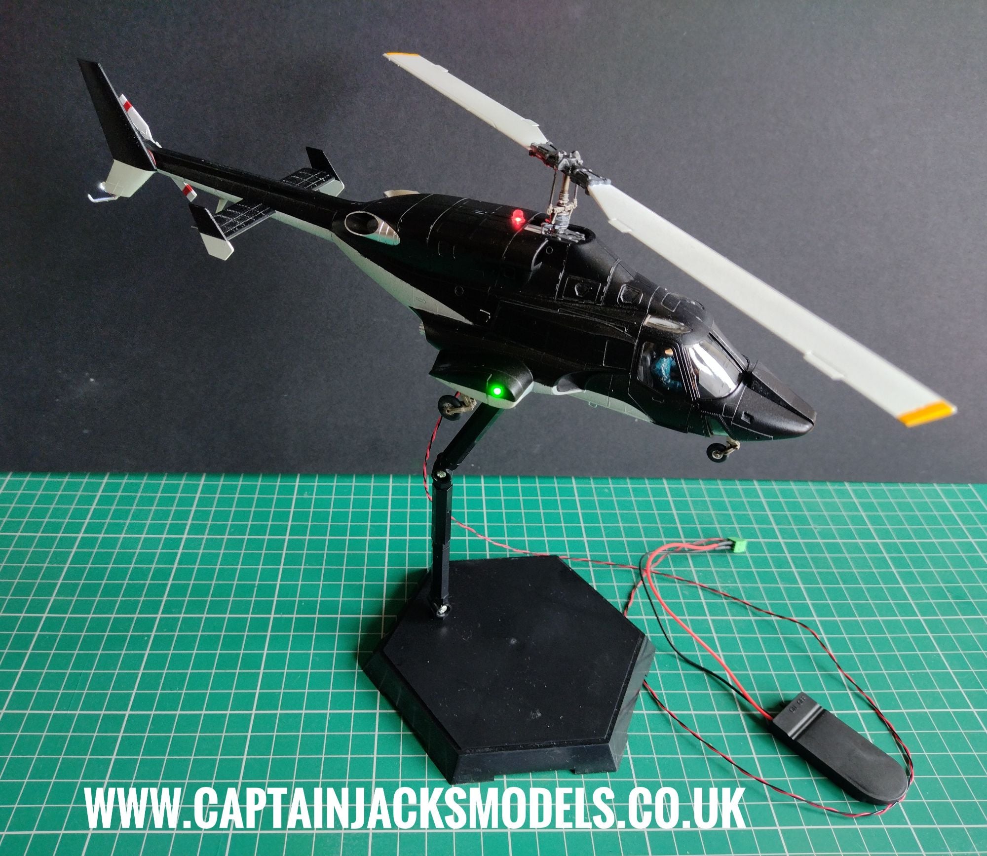
Aoshima AW-01 Airwolf Helicopter 1:48 Scale Prewired Light Kit Installation Guide

Additional Tools Required:
- 3.5mm Drill
- 1.5mm Drill
- Flush Cutters
- Tape to secure wiring
Please read fully through these instructions before starting the installation to get the best possible understanding.
Take your time with the installation of the light kit - This set contains very thin wiring and solder joints that can easily be broken if trapped between the model seams.
Step 1
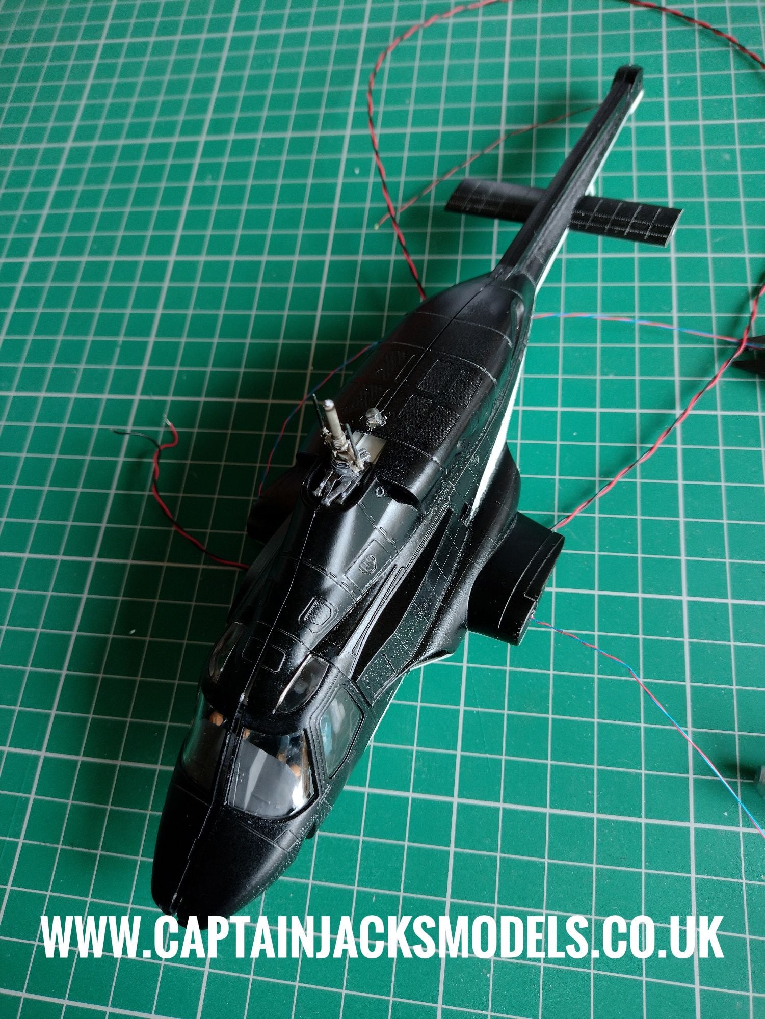
Place the two halves of the fuselage together. Use the 3.5mm drill to carefully widen the hole in the shell behind the rotor unit where the flashing red beacon led will be housed.
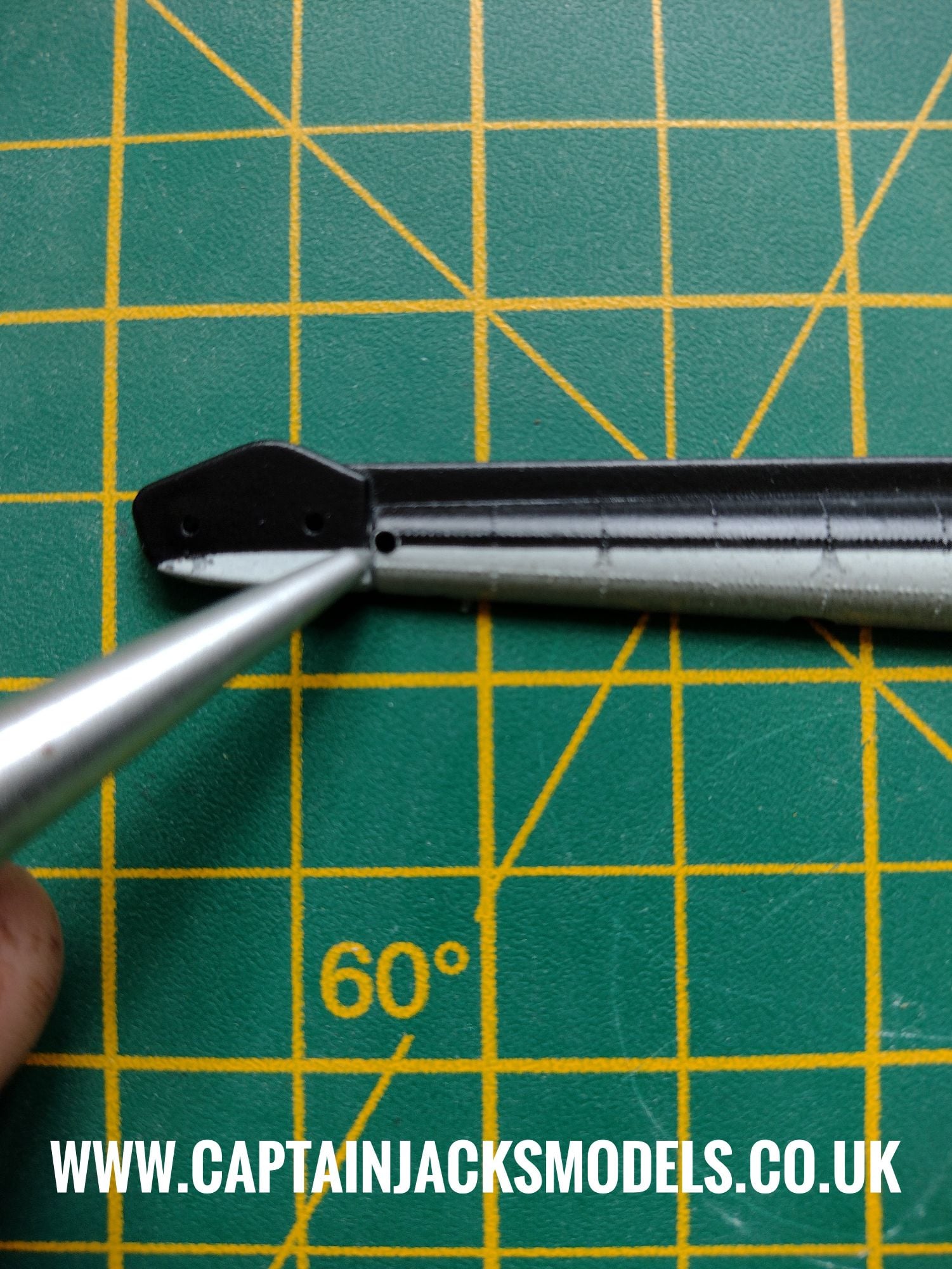
Step 2
A small 1.5mm hole needs to be drilled in the fuselage half to which the tail fin attaches as shown, through which the cool white tail beacon led wires will run.
Step 3
After assembling the cabin unit, drill a 1.5mm hole in the roof in the position shown, through which to feed the warm white led. This spot is ideal as the full glare of the light can be concealed behind the side panel, and the led aimed towards the back of the cabin to give a more subtle effect.
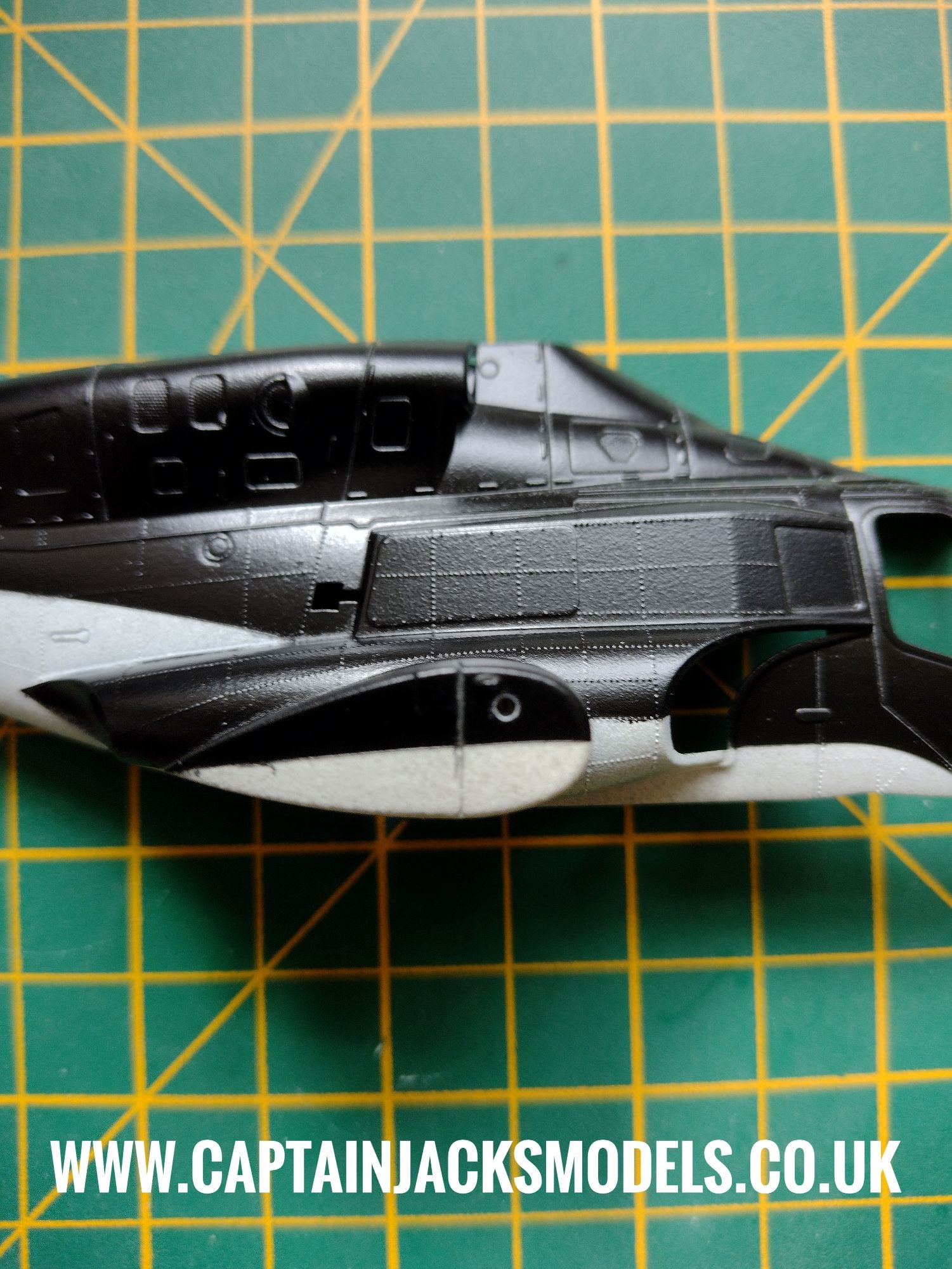
Step 4
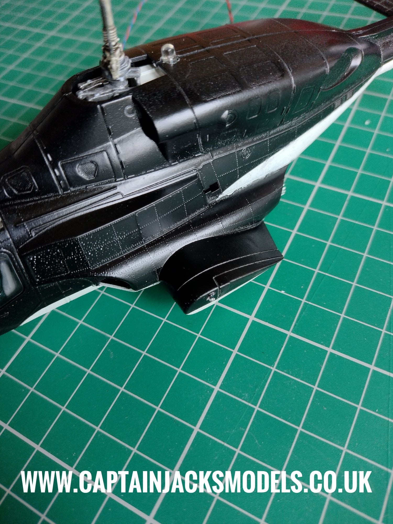
Assemble the gun port covers on each half of the fuselage, and drill a 1.5mm hole as shown straight the way through to the interior for the navigation light leds on each side.
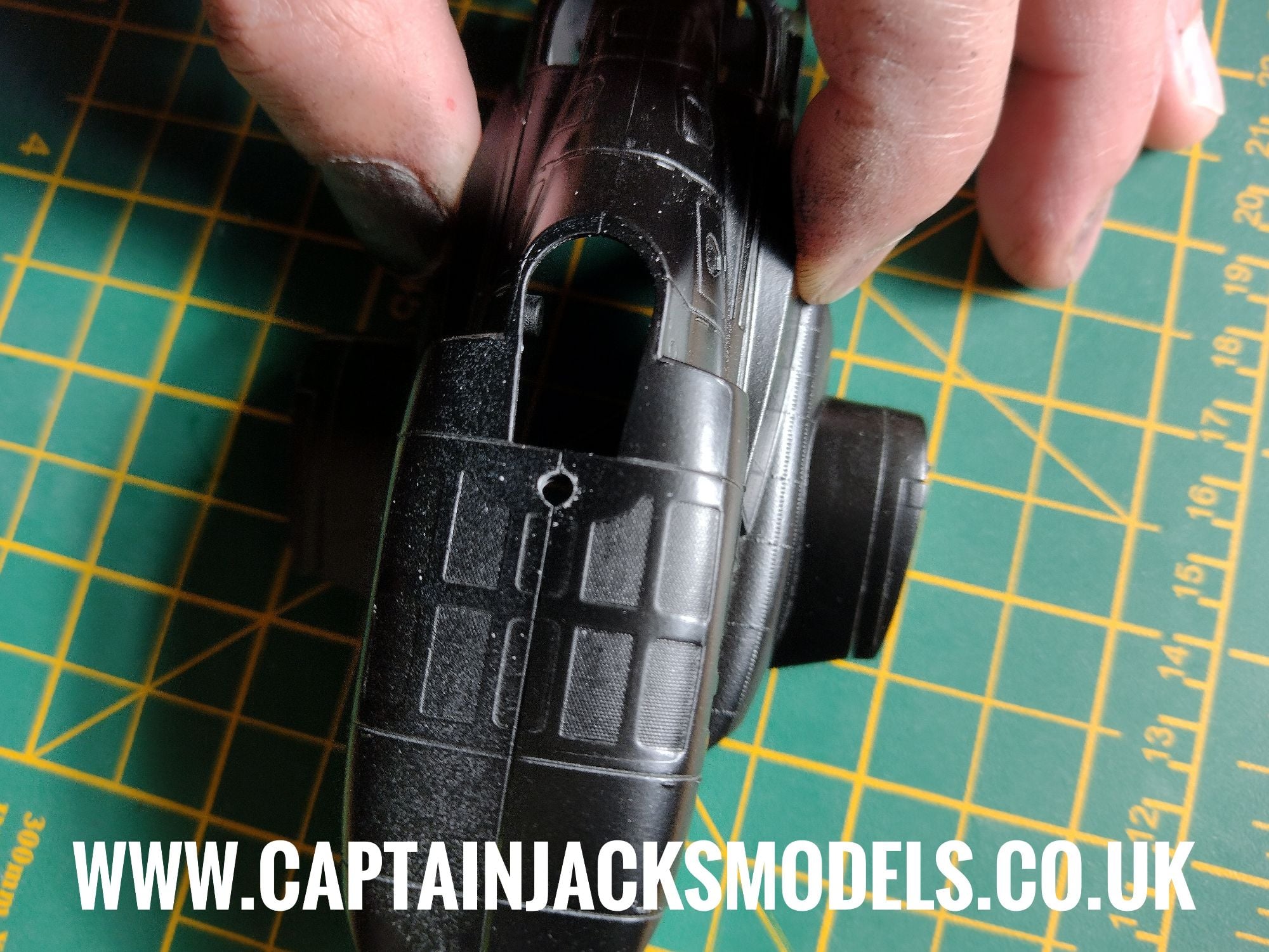
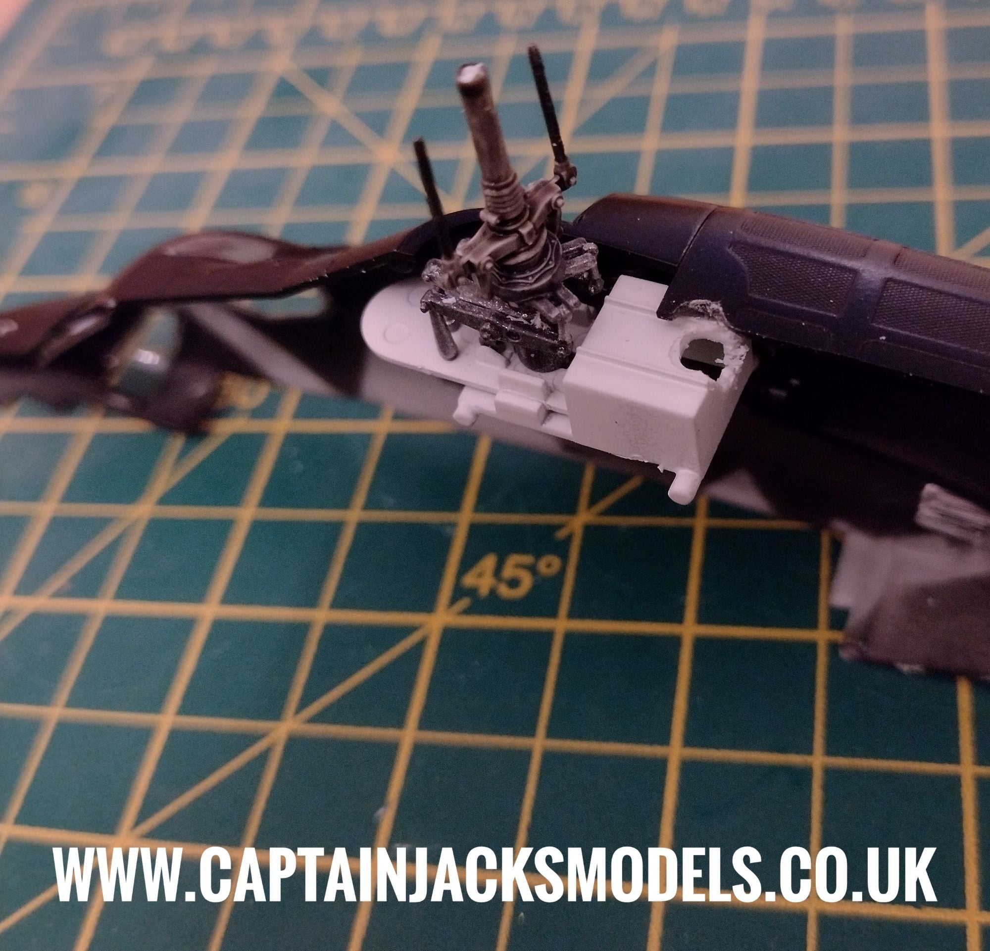
Step 5
Assemble the bottom half of the rotor unit and glue into place. The space in which to install the flashing red 3mm beacon here is very tight, so the area on the white rotor housing below where the beacon sits needs to be carefully drilled / nibbled out with cutters to accomodate the led and wiring as shown.
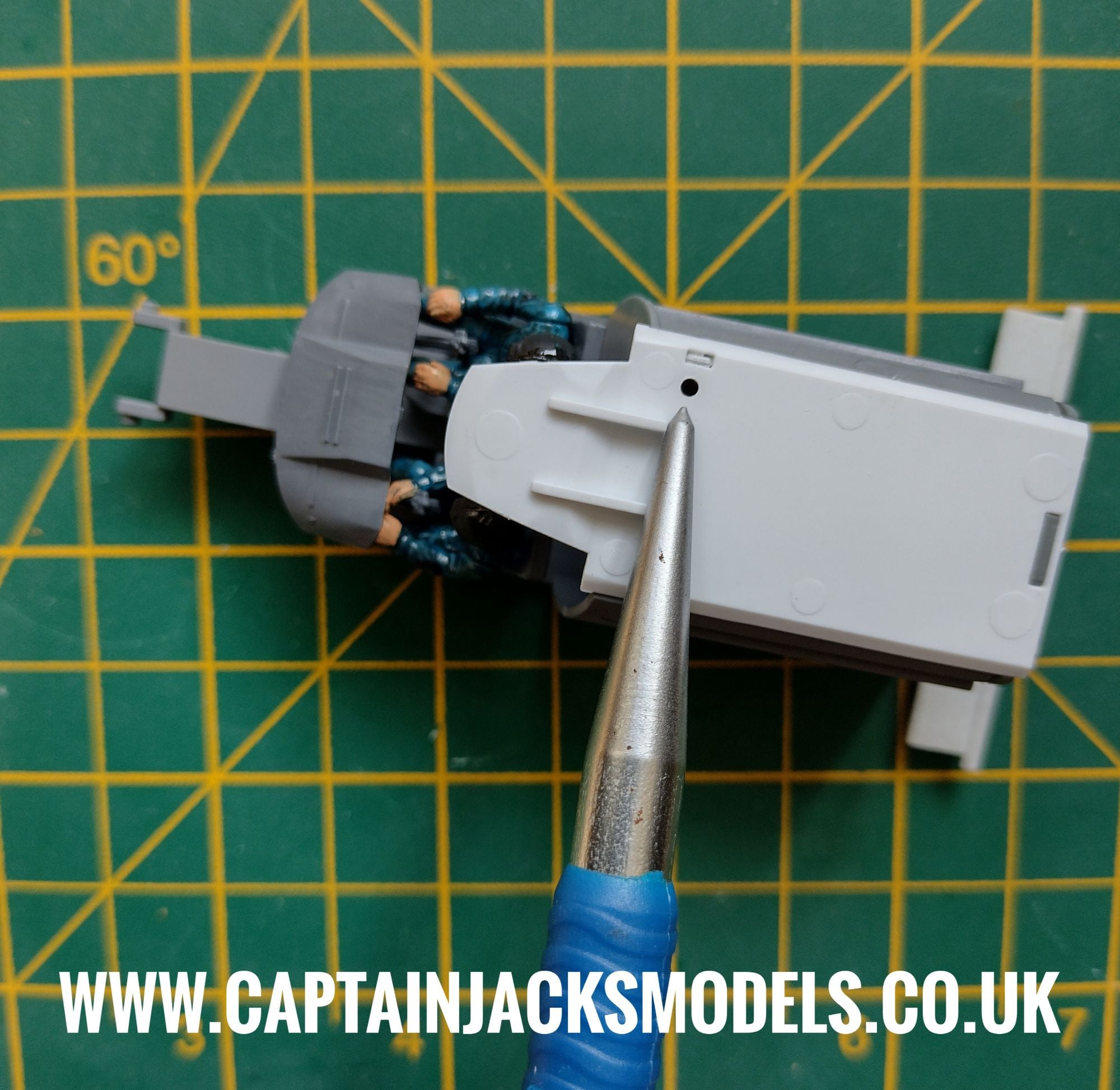
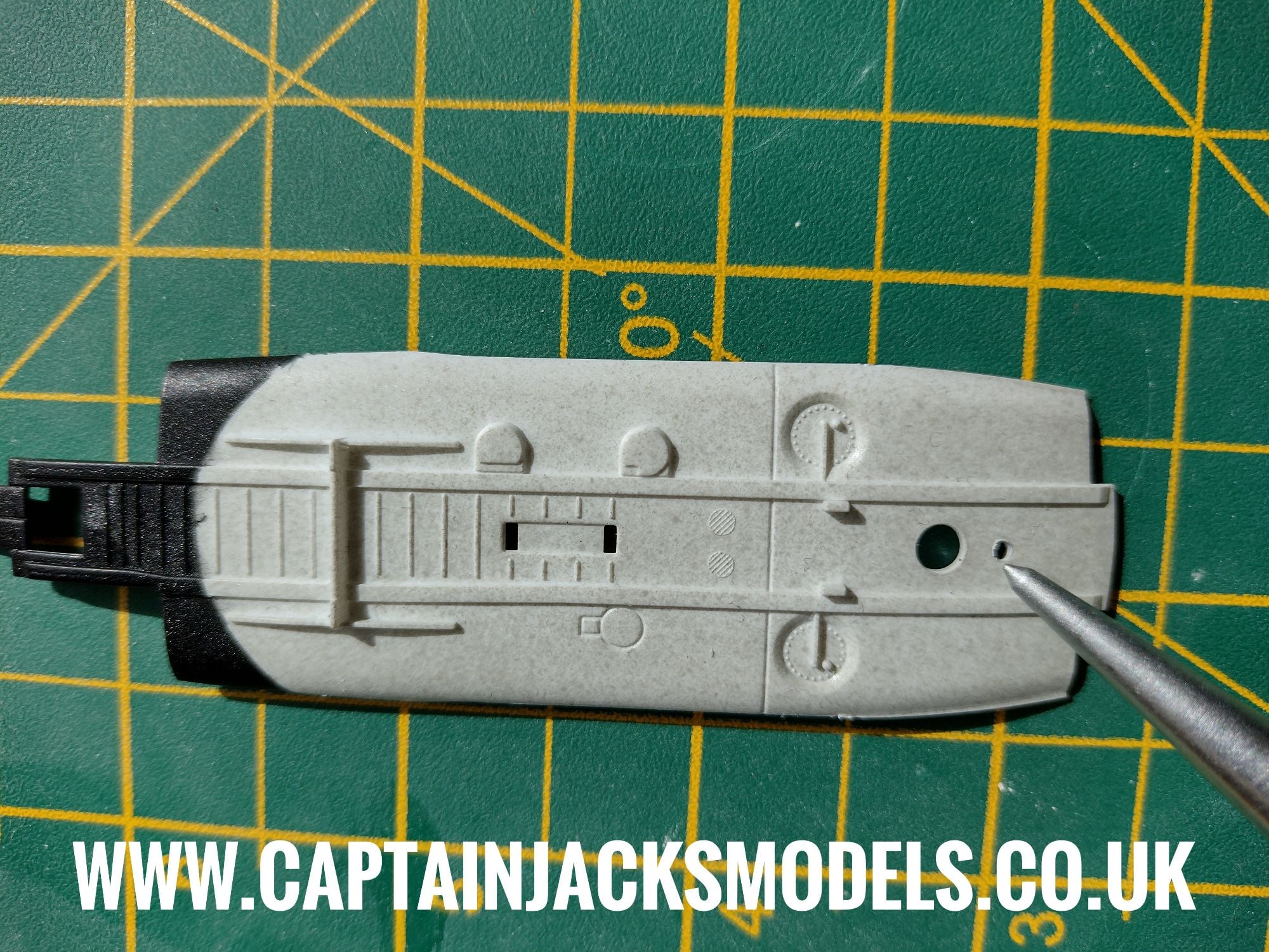
Step 6
A small 1.5mm hole needs to be drilled in the white base section of the fusealge that fits to the cockpit unit as shown, directly behind where the stand will attach. This is to run the power lead wires to the model base.
Place two CR2032 button cell batteries in the battery box observing the correct polarity and switch on the light kit to identify the led colours - the light kit is then ready to install.
Please note that the green screw terminal connector is used as it is the correct type for finer wiring. To release the wires, turn each screw anti-clockwise. The unit re-secures by moving upwards when the screws are turned clockwise, as opposed to larger terminal connectors that push down on the wires to secure them.
Step 7
Select the right-hand half of the fuselage (the side to which the tail fin attaches), remove the adhesive liner on the light kit circuit board and place in the fuselage as shown below.
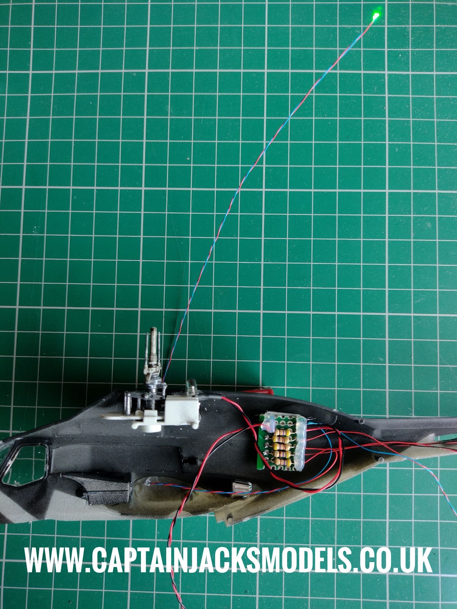
Step 8
Select the cool white micro led, and feed the led and wiring through the additional 1.5mm hole made in the tail section.
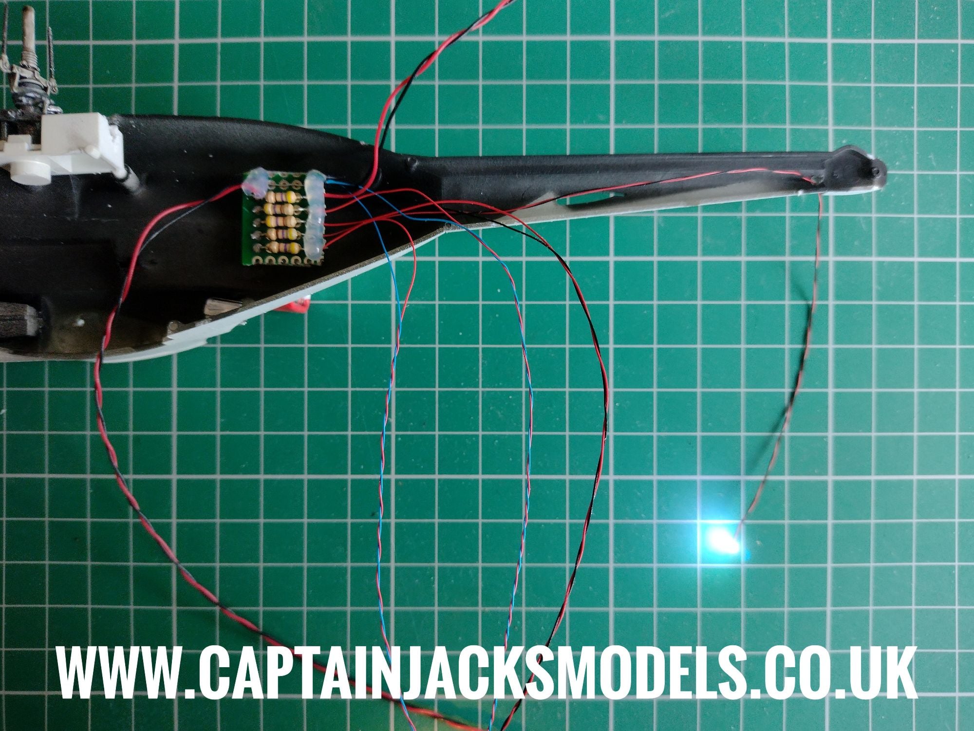
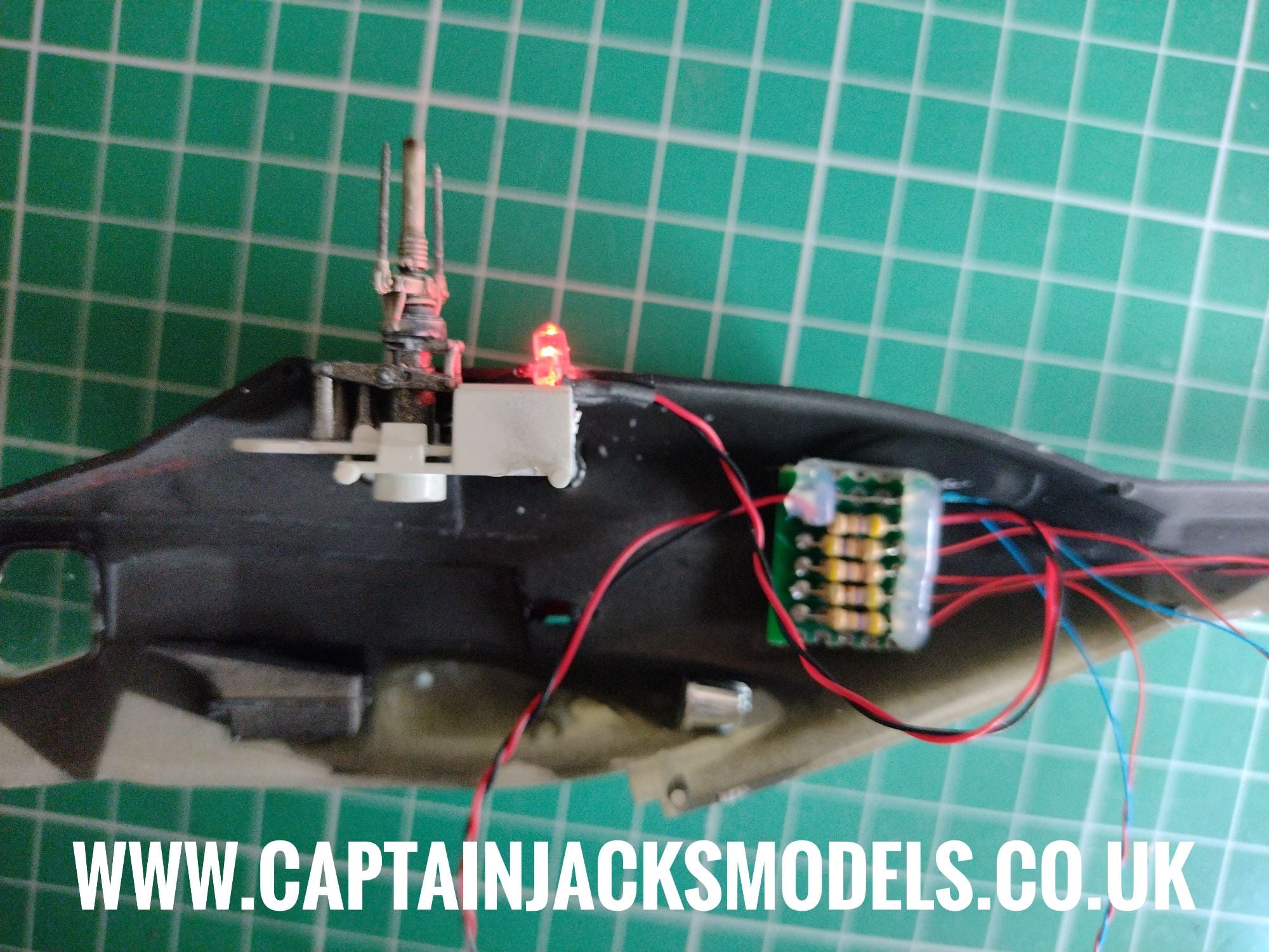
Step 9
Place the flashing red led behind the rotor unit as shown. Take time to double check the fit of this led now and remove any excess plastic that may make the fitment of the two fuselage halves more difficult later. The led should be fitted half way into the fuselage section, with the 3.5mm drill hole giving a little extra wiggle room without making things noticeable.
Step 10
Feed the green navigation light led and wiring completely through the side of the fuselage as shown.
Step 11
Feed the warm white led into the cabin section as shown, angling it towards the rear of the aircraft. When happy with the position, secure the wire using tape on the upper section.
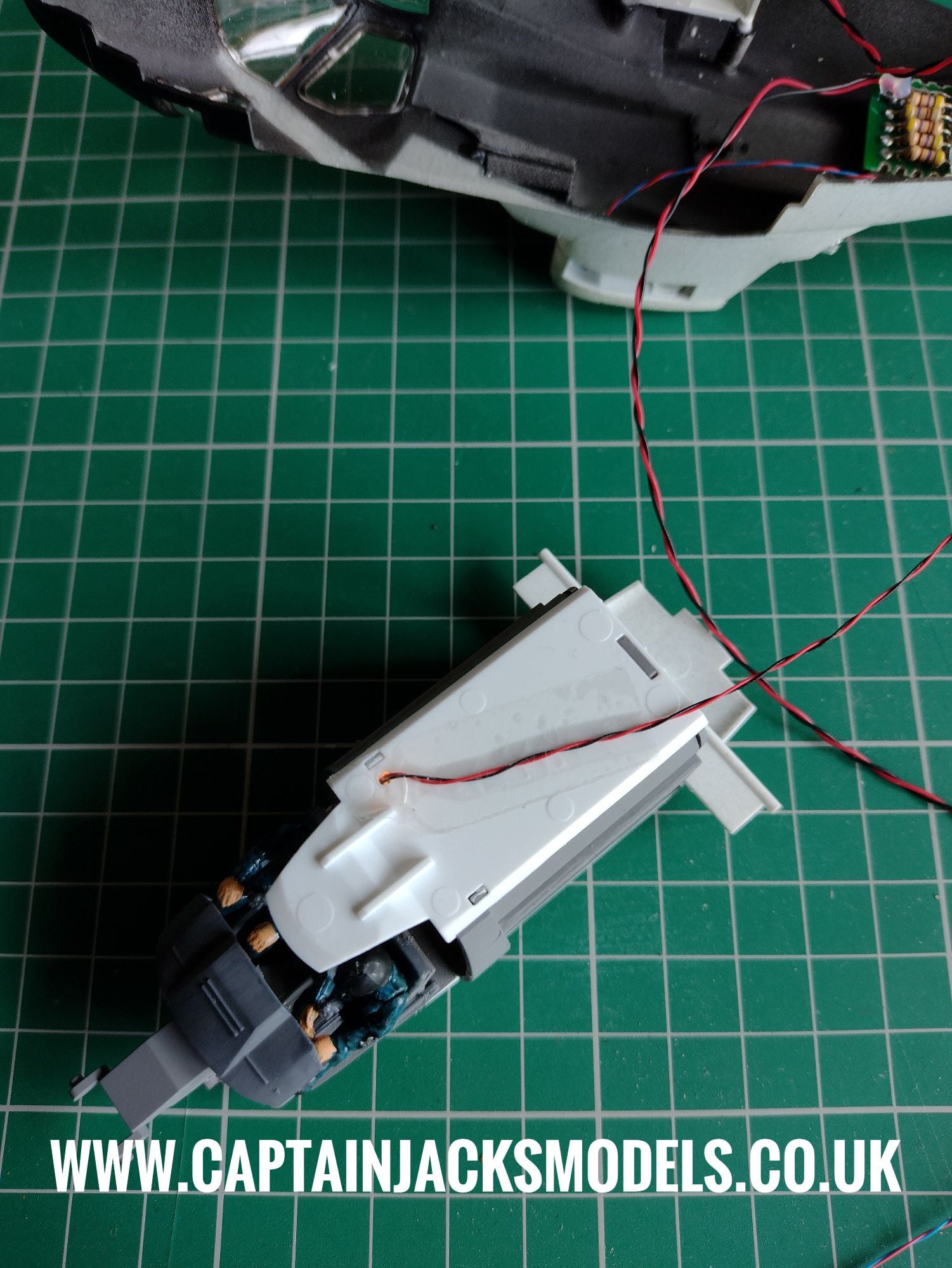
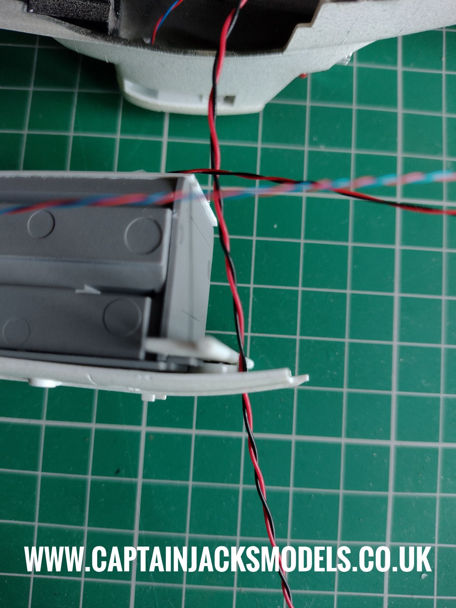
Step 12
At this point you'll be left with just the red navigation light led. Switch off the battery box and undo the wiring at the green terminal connector. Feed the power lead through the 1.5mm hole made in the cabin floor as shown.
Step 13
Glue the cockpit / cabin section into place as shown.
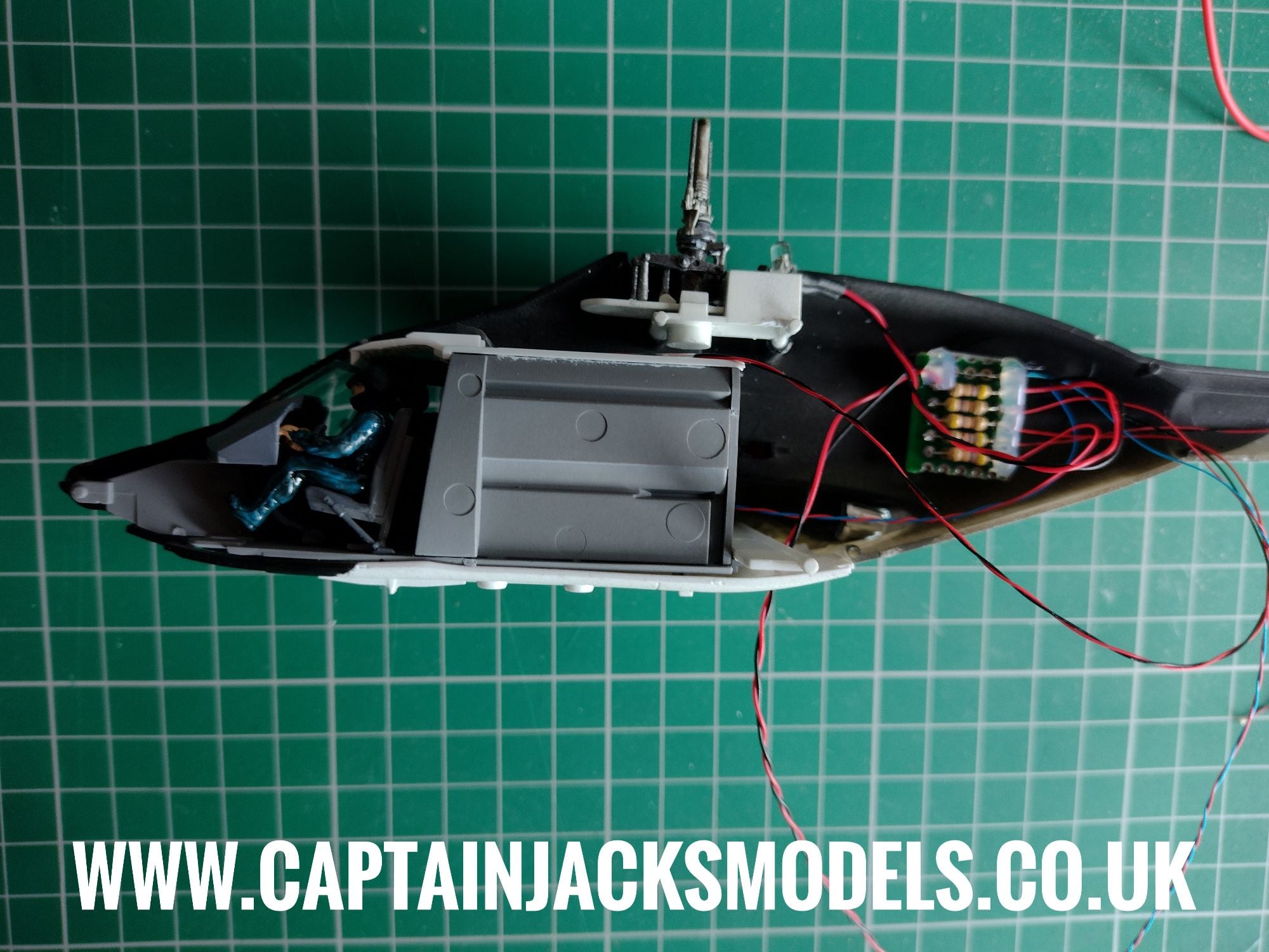
Step 14
Place the cross-section of the tailplane into position, ensuring the wiring routes comfortably around it. There is no need to glue the tailplane section.
Step 15
Install the red navigation light as shown in the other fuselage half.
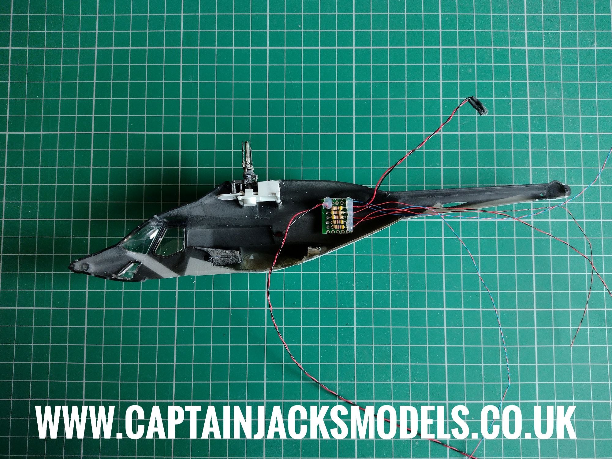
Step 16
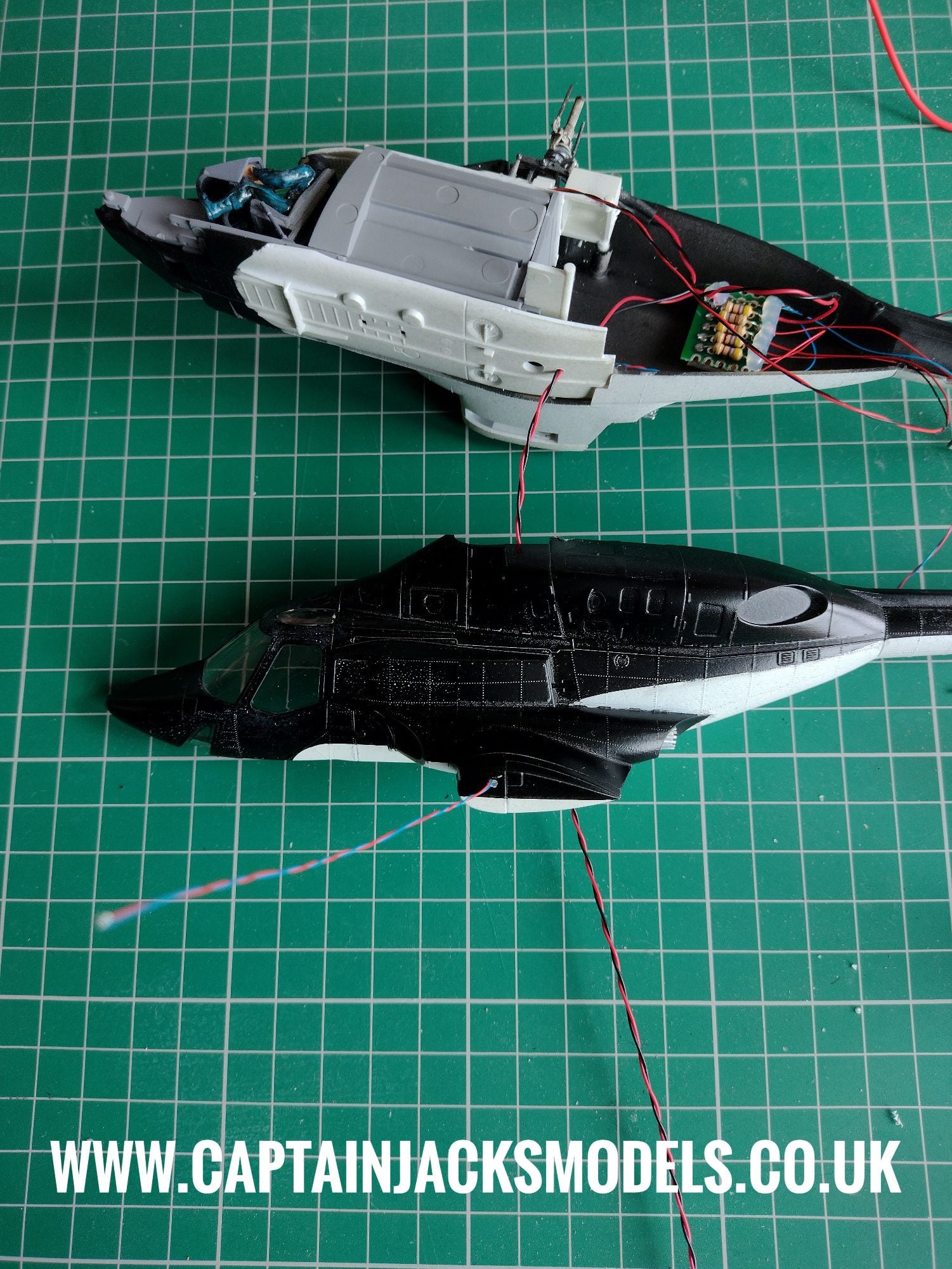
Double check the wiring positions ensuring that no wires will be trapped between the two fuselage sections when assembled. The wiring is very fine and can easily be sheared in the seams, so its worth taking extra time and care at this point.
Leave as much of the wiring as needed outside the model for the navigation and tail lights. You will see that I've already painted the fuselage on this model, as the model itself is a very precise fit and its a method that works well enough for me. Leaving the leds proud gives the option of assembly then painting at this point if preferred.
Step 17
When the main paintwork on the shell is completed, the red and green navigation light wiring canbe carefully pushed back inside the model, and the led glued into position as shown. Be careful not to feed the leds in too far so that they accidentally fall inside the model.
Step 18
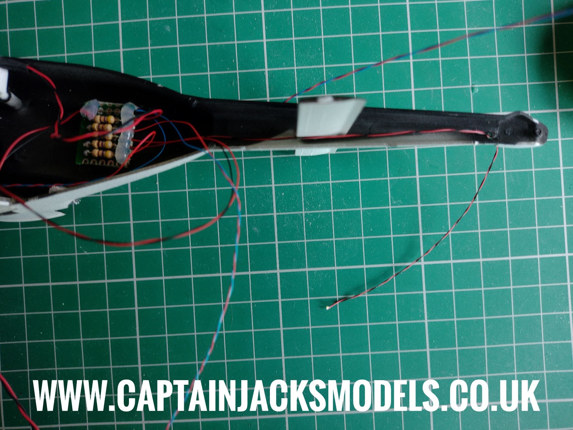
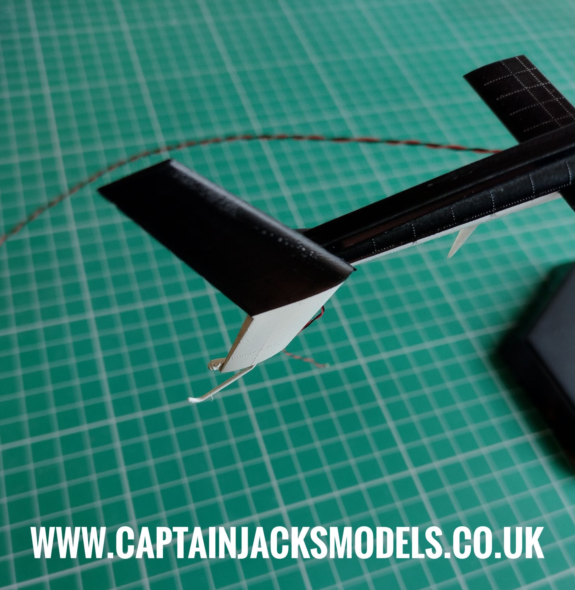
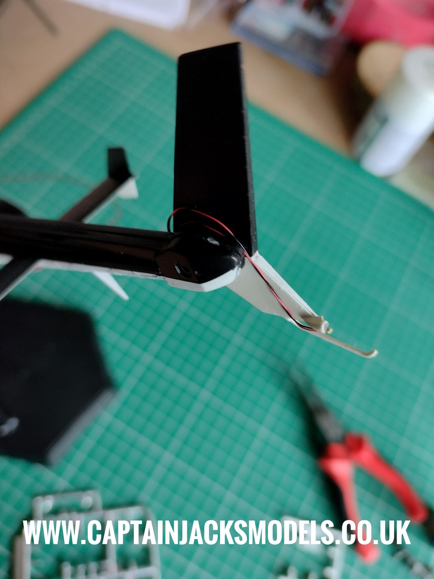
Now the tail fin needs to be attached and the white led fitted. As there's a small gap between the tail and the fin section when attached, it is much easier to wind the excess wiring around the tail section as shown instead of trying to push the wiring back into the tail itself.
The led then needs to be carefully glued in place on the lower tail section as shown. For a fully professional build, the way to conceal the wiring running down the tail fin would be to initially assemble the two tail fin halves, and then dremmel cut a fine channel down along the wire run. Assemble, add the led and wiring, putty and then paint. It's all down to personal preference and extent of the work you want to put into the model.
The wiring shown in the photo below is loosely wound to show position, and could be painted to conceal it as an easier option.
Step 19
Add the model to it's stand or diorama base, and trim the power lead wire to the required length. Reattach the lead to the green terminal block, ensuring red wire runs to red, and black to black. Remember that the terminal connection pull upwards rather than compress.
Step 20
Installation of the light kit is now complete. Continue to detail the model as required to personal prefence.